


€0,00
All about studio lighting
Waar bent u naar op zoek?
Frequently asked questions
1 EVERYTHING YOU WANT TO KNOW ABOUT STUDIO LIGHTING
2 STUDIO FLASH BASICS
Good studio flash systems differ from on-camera flashes in many ways. In addition to providing considerably more flashpower, studio units are designed to be used with a wide variety of light shaping accessories such as umbrellas, softboxes, grid spot attachments, barndoors, beauty dishes and others. Each of these accessories provides a different quality of lighting, allowing the user to precisely compose light to suit his purpose. Studio flash units are often used in multiples, with as many as four or more lights often used to obtain intricate combinations of light and shadow. The wide variety of setups involving studio lights demands that the user abandon Automatic Exposure Settings in the camera. Cameras must be set to Manual Mode with aperture and exposure time set manually. The power levels must be adjusted on each light separately in order to compose the scene, and a flashmeter is generally used to determine the appropriate camera lens aperture setting.

In order for the photographer to be able to visualize what the scene is going to look like when the picture is taken, studio flash units contain Modeling Lamps. These are incandescent lamps of modest power that are placed in the studio flash in such a position as to mimic the light that will be emitted by the flash when the actual picture is taken. There are certain considerations that must be met if the photographer is to be able to rely on his modeling lamps to provide a What-You-See-Is-What-You-Get (“WYSIWYG”) preview of the actual shots. Some manufacturers ignore the requirements for truly accurate modeling lamps. This can result in exposures that don’t look like what the photographer expected and the requirement of many test shots and adjustments in order to achieve a certain lighting effect. Accurate WYSIWYG modeling dictates the following: 1. Modeling lamps must accurately track flashpower adjustments in order to provide a constant relationship of modeling Lumens to flash Lumenseconds, with errors no greater than 1/10 to 2/10f at any power setting. 2. Modeling lamps must project similar beam patterns to the flash. 3. Modeling lamps, like the flash, should be immune to variations in power line voltage in order to maintain consistent accuracy regardless of fluctuating power lines. In this regard, all Paul C. Buff, Inc. studio flash systems employ high-precision voltage regulation of both modeling lamps and flash to provide consistent output at all power line voltages from 105 to 135 Vac. We are not aware of any other manufacturer that provides any voltage-regulation of modeling lamps whatsoever and are aware of several whose modeling lamps fail to track flashpower, with errors of up to 3/4 f-stop or more – far too much error for effective visualization.
Studio photography requires a wide and controllable range of flashpower in order to meet all lighting and aperture requirements demanded by a given session. Typical flashpower requirements can range from 5 or 10 Wattseconds (Ws) per unit up to 600 Ws or so. Outside the studio, when shooting in larger spaces, power requirements can be as high as 2400 Ws or more. Such power levels usually dictate the use of separate power packs and flash heads because of size and weight restrictions. It is paramount that the studio flash units have a suitable base power range for the type of work anticipated, and be capable of a wide range of power adjustment with excellent accuracy, consistency and modeling lamp tracking. We recommend 160 Ws to 320 Ws units for small studios and 640 Ws units for larger studios. If you have too much power, you may not be able to dial the power down enough to get low aperture numbers with close light to subject distances. All Paul C. Buff™ studio flash units have a minimum 6 f-stops power variability range (from Full Power down to 1/32 power), and some models feature additional power range switching to extend the adjustment range to Full to 1/128 power or more.
Flash durations should be no slower than 1/800 second (t.5) for general studio use, but should be considerably faster than this if any sort of sports or dance or other photography involving moving subjects is anticipated.
Studio flash units should mount to standard studio light stands with a 5/8” mounting post and should accept standard umbrella shafts up to 3/8” diameter (9mm). Umbrellas should mount as close as possible to the lamp axis for symmetrical umbrella patterns, and umbrellas must swivel with the flash unit. Studio flash units should be a capable of “bare-bulb” configuration and be fitted with a secure attachment mechanism that allows mounting a wide variety of accessories, including those made by third party suppliers. They should also employ a suitable swivel mechanism to allow the light and accessory to be secured at the desired angle. Paul C. Buff™ lighting products use an accessory mounting system that is common to all of our products and to Balcar products. Nearly all third party suppliers provide accessories fitting the Paul C. Buff™ / AlienBees™ / White Lightning™ / Zeus™ / Balcar standard.
Using monolights that have no remote control capability can be rather challenging for most studio photographers. Lights are often mounted in inaccessible positions where adjusting the power levels and modeling lamps can be quite difficult. A good remote control system can allow the photographer to critically adjust all the lights right from the camera position, even while looking through the viewfinder. Paul C. Buff, Inc.™ is an industry pioneer in the art of remote control systems. Essentially all products we have produced since 1986 employ a standardized remote control jack into which a variety of wired or wireless remote controls may be connected. Our current lines of remote controls (the CyberSync™ system and LG4X™ wired system) provide various control features for the AlienBees™, White Lightning™ and Zeus™ lines, from simply triggering to complex studio control. The second generation Paul C. Buff, Inc.™ flash units, begun with the release of the Einstein™ E640 flash unit, incorporate a receptacle for digital remote control connection (as seen with the CyberSync™ CSXCV transceiver).
Studio lights normally contain flash-sensitive slave cells that can be set to automatically fire the unit when it “sees” the flash from another. This allows the user to sync only one light to the camera, allowing all other lights to then fire simultaneously without additional sync connections.
In order to allow for bright modeling lamps and all-day shooting with a variety of accessories, studio flash units should be provided with cooling fans to avoid overheating problems.
3 FLASH DURATION
FLASH DURATION
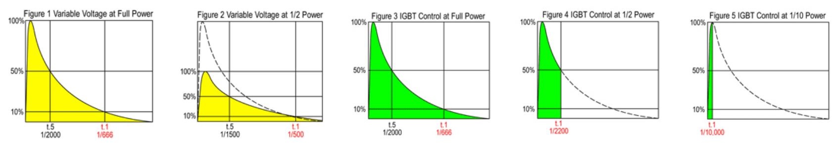
Figure 1 depicts the typical characteristics of a Xenon flashtube. When the tube is fired there is a rapid ionization period as the tube output rises to maximum brightness. This is followed by an exponential decline in tube current, voltage and light as the capacitors are discharged to zero. The standard engineering term for stating flash duration is “t.5”. This describes the time it takes for 50% of the total flashpower to be dissipated. Whenever the simple designation “Flash Duration” is specified it can be assumed to be the t.5 spec.
However, the t.5 spec doesn’t adequately predict the actual motion freezing capability of a flash. There is a much longer trailing edge that continues to emit the remaining 50% of the light. This causes considerably more motion blur than the t.5 spec implies. In order to better compare flash duration specs to an equivalent shutter speed, the term “t.1” was introduced by the photo industry. t.1 specifies the time it takes for 90% of the total flash to be emitted. But even following the t.1 time there is still light being emitted at sufficient intensity to cause some ghosting or motion trails.
The vast majority of studio monoflash units, regardless of price, control the flashpower by varying the voltage to which the flash capacitors are charged. Variable voltage control is the primary method of flashpower control in our AlienBees™ and White Lightning™ X-Series flash units.
Figure 2 depicts such a flash when the power is reduced to 50%. Notice the discharge curve is similar to the Full Power curve, but that the intensity is reduced and the discharge time is slower. Both the t.1 and t.5 flash durations are longer because of the reduced voltage and flashtube current.
Another result of the reduced voltage and current is a lowering of color temperature that is proportional to the amount of power reduction via voltage variable means.
Flash units using variable voltage power control (including the Paul C. Buff, Inc. AlienBees™, White Lightning™ X-Series flash systems) typically exhibit an increase in flash duration roughly equal to 20% of the full power flash duration being added for each full f-stop in power reduction and about a 75K decrease in color temperature per f-stop of power reduction.
Essentially all low power camera flashes (speedlites) employ IGBT control of flash power instead of variable voltage control. This technology is easily implemented in low power units, but only recently have IGBT devices become available with sufficient power handling capacity for use in higher powered studio flash, especially those offering fast flash durations.
In looking at Figures 3, 4 and 5, it is seen that, in an IGBT flash, the voltage and current remain constant as power is reduced and that power is reduced by abruptly shutting the tube off once the desired amount of light has been emitted. This results in flash durations that become shorter and shorter as power is reduced, as well as the complete elimination of the exponential flash tail that is responsible for motion blur in non-IGBT flash units.
Notice in Figure 2 that a 50% power reduction in a conventional studio flash lengthens the t.1 flash duration from 1/666 second to 1/500 second while the same power reduction in an IGBT flash (Figure 4) shortens the t.1 duration to 1/2200 second and that the trailing edge tail is completely removed.
Figure 5 illustrates the extremely short 1/10,000 second t.1 time when the power is more dramatically reduced.
It should be understood that the color temperature of a flashtube is, in part, determined by the voltage and current at which it is operated. In Figures 1 and 3, the color temperature emitted is not constant throughout the discharge period. Rather, the color temperature is higher (more blue) at the beginning of the discharge and becomes lower (more red) as the waveform declines. Thus, it is the average of the beginning and ending color temperatures that form the effective color temperature for the exposure.
Speedlites typically produce higher and higher color temperature as power is reduced because of discarding the lower color temperature “tail” and keeping the higher color temperature initial portion.
The Einstein™ E640 flash unit: When used in its CONSTANT COLOR mode, Einstein™ combines IGBT shutoff of the flashtube with an exacting digital adjustment of the capacitor voltage in order to achieve a constant 5600K +/- 50K color temperature at any power setting (when used with the 5600K flashtube). In ACTION MODE, Einstein™ allows the color temperature to rise slightly as power is reduced as a means of achieving the fastest possible flash durations. Both the t.1 flash duration and the color temperature are displayed on the rear panel LCD in all modes and at all power settings.
4 COLOR TEMPERATURE AND COLOR BALANCE
In order to achieve good color balance with studio flash, the user must understand the factors that affect color.
Cameras with built-in flash need only establish color balance parameters from a single, unchanging flash source and are normally set to “flash” setting for proper color.
But color balance with studio flash is affected by a number of variables including the color balance of the flash units themselves, changes of color introduced by the shooting environment, changes caused by light modifiers and the artistic perception of how colors should look in a shot.
The first rule of seasoned professionals is that there is no reliable camera setting that considers all of these factors. The assumption that all lights rated at a certain color temperature (such as “5600K”) produce the same color balance is incorrect. In particular, the “flash” setting of most cameras is not accurately matched to most studio flash systems. There is simply no automatic method of setting accurate color balance in the camera. Fortunately, there are two methods of easily achieving good color balance.
The proper method to do this in the camera is to follow the camera manual’s instructions for setting a Custom White Balance. When you do this, a test picture is taken with the lights set up and adjusted for the pictures you are about to take. The camera then calculates the appropriate adjustments needed to render neutral colors (greys and whites) taken in this lighting environment free of colorcasts and errors. Once this is done, the entire color spectrum will be reproduced as accurately as the particular camera allows for. Using custom white balance is the preferred method of color balancing if you are shooting jpg pictures or when you wish to avoid post processing of your shots.
With the evolution of software programs such as Adobe Photoshop, most professionals prefer to shoot their important sessions with the camera set to “RAW” mode rather than jpg. This method saves the information directly from the camera sensor to the memory card, bypassing any processing in the camera. Thus, you can shoot spontaneously and avoid all color balance, contrast and sharpness settings in the camera with the assurance you can more accurately set these parameters after the fact, in post processing. A word of warning: Shooting in RAW cannot undo burned out whites, out-of-focus shots or improper ISO and shutter speeds settings from the camera and thus requires you to set these parameters properly in the camera. The proper method for shooting RAW is to make sure that you have a known-neutral object in the scene. If you are shooting a series of pictures under the same illumination, you can place a white or grey white-balance test card in the first shot of a series, then remove it for subsequent shots. Many shooters prefer to leave a white balance card at the top or bottom of every shot where it can be cropped out later, as this gives them the freedom to make significant changes in the lighting with the assurance each shot can be critically color-balanced in post processing. If you are shooting against a neutral grey or white background, you can often omit the white balance card and use the background as a neutral object. But beware that all grey or white backgrounds are not truly neutral and that filters, gels, etc. must not tint the light falling on the background. The procedure for post processing RAW shots is really quite simple. In Adobe Bridge (part of Photoshop CS2 and CS3), you can open your entire folder of pictures. Select a picture that contains a white balance card and simply place the eyedropper tool on the white or neutral grey portion of the card. The software will instantly calculate perfect color balance for the entire image. From there you can adjust contrast, exposure, cropping, sharpness and other attributes of the shot. If you have shot a series of pictures under the same illumination, you can then copy and paste any or all of these parameters to all the other shots in the series. In RAW processing, the original image data is normally saved to the hard drive and a copy of the image containing your adjustments is output to a new file as jpg, tiff, Photoshop or other file type. If you are later unhappy with your post processing it’s an easy matter to reopen the image in RAW, apply new settings, and output new final files. Smart shooters always archive their original RAW shots.
It is quite possible for softboxes, brolly boxes and umbrellas (as well as other fabric or paint-based accessories) to produce either warmer or cooler color temperature, even from batch to batch. This is typical with most all fabric-based accessories - the vendor buys the fabric and the fabric supplier gets it from different batches. It's pretty hard to control - even for the most expensive brands. The same is true with basic flash color temperature and cameras. 5600K might be neutral on one camera and 300K-400K off on another camera. There is also a green/red component of color balance that is not stated in the basic color temperature specs, so even an exact match in color temperature alone will not yield perfectly neutral color balance. There is a lot of controversy about this subject, and the consensus is that one cannot rely on color specs or camera settings to achieve perfect color balance - with any lights or accessories. The consensus also is that all accessories will alter color balance by up to several hundred degrees. The only way to properly color balance is to do a custom white balance in the camera or, preferably, to shoot in RAW and color balance in Photoshop or other RAW program.
5 SYNCING TO THE CAMERA AND SYNC SPEEDS
Firing a studio flash from the camera requires some form of instruction from the camera to tell the flash when to fire. This can be done with a sync cord, with a remote control or, in some cases, by letting the camera fire its own built-in flash to set off the flash-sensitive slave trippers contained in most studio flash units.
But it is difficult or impossible to set the built-in flashes on many cameras so they fire at the right time. Most digital cameras use a “preflash” to set automatic exposure, for redeye reduction or to determine color balance and other settings. Unless the preflash can be disabled in the particular camera, it will trip the studio flash units prematurely and they will not expose the shot. Many cameras, including the popular Canon Digital Rebels, have no facility to disable the preflash and therefore cannot be used to trip studio flash from the camera flash.
These cameras and many others also lack a standard sync terminal to connect a studio flash, but most cameras do have a standard hot shoe. In order to connect a sync cord to such a camera, you may need a hot shoe adapter. This adaptor provides a standard sync connection to which you can connect the sync cord provided with most studio flash units. However, the standard “PC style” photo sync cord connection is notoriously unreliable. They become loose, fall out and make poor connections regularly.
Because of the unavoidable unreliability with the PC sync connection, we highly recommend our CyberSync™ Radio Remote Control System for syncing our studio lights to the camera. The tiny transmitter slides right onto the camera hot shoe and runs typically for a year or more without changing batteries. A CyberSync™ receiver may be attached to one of the studio lights and when that light fires, any other studio flash units will also fire via their flash-sensitive slave trippers.
If you wish to make flashmeter tests from various positions in your shooting environment, it’s a simple matter to slip the CyberSync™ transmitter off of your hot shoe and carry it around with you to test-fire the lights. Or, you can invest in a second CyberSync™ transmitter expressly for this purpose as well as for backup.
If you are shooting in locations where other photographers are also shooting, you might want to use a separate CyberSync™ receiver for each of your lights and disable their slave trippers.
First, successful studio flash use normally dictates that you turn off all automatic functions in the camera and shoot in full manual mode with a fixed ISO setting (preferably ISO100 for highest resolution and minimum noise). This will require you to set the aperture and exposure manually. A decent flashmeter is the easiest way to determining proper aperture settings.
Perhaps the most frequently asked question from studio flash users is “Why is there a black band across part of my picture?” The answer to this lies in the camera itself. Nearly all shooters are using cameras with focal plane shutters. The black band is caused by the shutter partially blocking the sensor when the flash fires.
A focal plane shutter exposes the image by moving two light-blocking curtains across the front of the image sensor. The first curtain slides open to begin the exposure, then the second curtain slides closed to terminate the exposure. In order to expose the picture from a flash, both curtains must be open at the time the flash is fired.
As you shorten the camera’s exposure time a point is reached where the first curtain is not completely open before the second curtain begins to close. The effect becomes a “moving slit” that slides in front of the sensor at this critical exposure time setting. Thus the camera maker specifies a maximum sync speed that assures both curtains will be completely open when the flash is fired. If the flash is fired at shutter speeds faster than the maximum flash sync speed part of the sensor will be blocked by one of the curtains and part of the shot will be blacked out.
The maximum flash sync speed varies from camera to camera, with most modern digital SLR cameras being rated between 1/125 and 1/250 second. In order to avoid the black bars, you must not exceed these speeds. You must also consider any delay that might be introduced by radio remote controls since these can introduce a small delay between when the camera sends the fire command and when the flash unit actually receives it. It is therefore prudent to set the camera shutter speed somewhat below the published maximum flash sync speed. If your camera is rated at 1/200 second, shoot at 1/125 second to avoid problems.
Many shooters don’t realize that in typical studio usage it is almost solely the flash duration of the flash unit that determines action stopping. This is because the brightness of the flash is typically hundreds of thousands brighter than the ambient studio lighting and modeling lamps. So, even if you shoot at 1/30 second shutter speed, the ambient light is generally so much weaker than the flash that it doesn’t contribute to the exposure. Setting the shutter speed at 1/60 to 1/125 will almost always result in proper flash exposures with no black bars or motion-blur.
This situation changes when you are using flash outdoors or in areas with extreme amounts of ambient light. Here, the contribution of ambient light can approach or exceed the flash exposure and must be balanced and controlled.
If, for instance, the camera meter reads f8 at 1/60 second from the ambient light and you wish to use fill flash to bring the subject illumination up to f11, you would meter the flash and ambient light together, increasing or decreasing flash power until flash and ambient light together reach f11.
If you shoot a test picture under these conditions and see that you need more flash and less ambient, you can adjust the flashpower upward and shoot at a higher aperture to get the proper exposure. You can also move the shutter speed up to say 1/125 and leave the flashpower alone. The change in shutter speed will lower the amount of exposure from ambient light but will have no effect on the flash exposure. You cannot, however, set the shutter speed faster than the maximum flash sync speed or areas that are covered by the sensor will only be exposed by ambient light, not flash, and will appear darker. This may or may not be immediately as noticeable as when in studio where all light comes from flash.
This is tricky stuff. It is recommended the shooter endeavor to understand the relationships between ambient and flash and shutter speed and aperture and ISO, then do a lot of practicing. There are many good books on the subject.
These relationships are particularly important when shooting in sports arenas where the ratio of ambient to flash is considerable and where stopping action is paramount. Here, the power and flash duration of the flash are important. The flash must overpower the ambient light and the flash duration must be fast enough to stop action. This typically requires a t.5 flash duration of 1/1200 second or faster for good action stopping with as much flashpower as possible. Once again, shutter speeds faster than the camera’s maximum flash sync speed cannot be used to diminish the ambient light contribution or dark bars will result.
In high ambient light, you are still limited to your camera’s sync speed. If, at that speed, you get motion blur with ambient but no flash, that blur will still be present when using flash, regardless of flash duration.
6 LIGHT BEHAVIOR BASICS
There are fundamental properties of lighting that form the basis of our value judgments concerning its effectiveness. Many of these properties are not understood fully by the novice photographer, and even some professionals.
Contrast is the degree of separation between light tones and dark tones. In the basic context of defining contrast, we might think of a picture of a black and white striped surface as being “high contrast.” While this is the correct line of thinking, there is a far more complex relationship to lighting and subject matter and contrast than initially comes to mind. Consider as a model, for instance – a brown skinned person in a brown suit with a brown dog against a brown background. The amateur might think the contrast of this scene is established by the subject coloration, while the professional realizes the same scene may be shot with almost any degree of contrast desired, by manipulation of the lighting equipment. Besides the obvious placement of lights to form actual gradients, or variations of light intensity across selected parts of the scene, the surface textures of the various scene components can play an extremely important part in how the scene looks under certain lighting conditions. So that we fully understand lighting and texture and contrast, let us conduct a mental experiment: We shall use two light sources, each producing, say, 2000 Lumens. Light Source #1 is essentially a point source of light, measuring 1/4-inch in diameter. When we look at Light #1, it appears extremely bright and uncomfortable to look at. It appears bright since all 2000 Lumens are emanating from a very small surface area, having a very high “spot intensity.” For Light Source #2, we will place a 2000 Lumen lamp inside a huge sphere of diffusing material (white cloth, frosted glass, etc.), thus producing a very large light source, perhaps 10 feet in diameter. When we look at Light #2, even though it too produces 2000 Lumens, it does not appear nearly as bright, nor is it uncomfortable to look at. Its spot intensity is extremely low with respect to Light #1, though its overall intensity is the same. It is a large “soft” light source.
Now, imagine a room with one wall covered in fine white felt, a black wall opposite and a light in the middle. If we look at the white felt wall, it looks the same regardless of which of the above light sources is used. In either case, it is illuminated by 2000 Lumens and there are no surface reflections to give us a clue to the size or shape of the light source. If we replace the white felt with a large mirror, we see something entirely different. If we turn on Light #1, we see the same image as we would by looking directly at the light – a very intense spot of light. If we photographed this, we would have an extreme contrast image – a bright, overexposed spot, surrounded by a dark background. On the other hand, if we viewed or photographed the mirrored wall using Light #2, we would see a much lower contrast with a large soft glow of much lower spot intensity – a reflection of the large, soft light source. From this experiment, we can see that the surface reflectivity has a great deal of bearing on things. While both walls are colorless, the flat textured felt appears the same under either “point-source” or “large-source” light, while the mirrored (specular) surface looks entirely different under the two lighting conditions. If we replace the two walls with more common subjects such as the “all brown” scene described above, we will find that each surface, though brown, has its own degree of specularity, or surface reflectivity. The man’s face may have small beads of sweat and oil for instance, which form tiny mirrors. The brown shoes may be highly polished and the laces matte. The suit may have some shiny polyester threads. Given a certain level of scene illumination, the picture will appear entirely different depending upon the spot intensity and source size of the light sources – the smaller the light source (higher spot intensity) the more intense the reflections from the ”specular,” or reflective bits of the scene. Where the specular areas are relatively large and flat, such as the polished shoes, we will actually see a discernible reflection of the light source. Where the specularity resides in the much smaller textures, such as in the polyester threads, we will simply perceive glistening highlights. In any event, the highest possible scene contrast will appear as the lights approach point-source, while lower contrast and less surface definition will prevail under conditions of high light-diffusion. The degree of contrast we wish to convey via lighting is governed by the subject matter and artistic goals. Too-high contrast can result in pictures that are impossible to print, perhaps with glare and washed out areas or emphasized undesirable features such as wrinkles. Too-low contrast, caused by excessive diffusion, can lead to dull, uninteresting and undefined pictures. The answer is to first understand the principles involved, and learn the range of contrast that will print well and look good, and to know what it is you’re after. You can then use various combinations of diffused and direct light to achieve your goals.
The degree of light diffusion affects scene contrast in another way, via the introduction of shadows. Again using hypothetical light sources - Light #1 and Light #2, as well as the white felt wall, let’s conduct another experiment. This time, let’s place a new object, say a person, in front of the wall. Using Light #1, all light that falls on the scene comes from a single point. Wherever there is an obstruction, a distinct black shadow is formed. The person’s shadow appears on the wall, and dark shadows form under the chin, behind the nose, etc. The contrast is very high when the brightness of the highlights is compared to the blackness of the shadows. Wrinkles become pronounced due to the dark shadows that form with each “hill and valley” of the skin. If we now substitute Light #2, the shadows soften or nearly disappear because the light is coming from many angles and “wraps around” any surface obstructions. Since there are no longer any deep, dark shadows and the reflections from specular surfaces are subdued, the ratio of highlight intensity to shadow intensity is much lower – lower contrast and less defined features result. Again, overly small light sources produce excess contrast (a hard look), while an excessively large light-source produces a soft, featureless result
Thus, while there are two distinctly different mechanisms working to associate contrast with size of the light source(s), they both work in the same general direction. To illustrate that there are, in fact, two separate parameters, and to show that they can be controlled independently, let us set up a third hypothetical lighting situation: This time, assume there are 10 point-source lights, each producing 200 Lumens, arranged in a broad array about 3 feet square in front of the subject. From the standpoint of shadow formation, there will be essentially as much “wrap around” effect as would be obtained with a 3-foot diffusion panel. Since the light will come at the subject from a broad range of angles, there will be no deep black shadows, rather a multiplicity of distinct shadows that blend to form a soft overall shadow structure. As far as specularity is concerned, while each 200 Lumen light has only 1/10 the spot intensity of a single 2000 Lumen light, the spot intensities are still hundreds of times greater than would be evident with a 3-foot diffuser. Each light is quite capable of producing strong reflections from shiny components of the subject. What’s more, when we are dealing with surfaces containing a large number of tiny reflective particles (perspiration, sequins, metallic threads or generally reflective surfaces of angular form such as lips, eyes, small objects), the multiplicity of small “pin” lights will produce ten times as many specular “glints” than would a single, point-source light. Thus, while the reflections are not as intense, there will be more of them. The net result of this lighting scheme should be a picture that has a high apparent contrast and specularity, yet one that reveals no hard shadows and is much easier to print than a picture made with a single point-source light. Notice, the parameter that causes the relatively high contrast has been isolated to the reflective component, while the shadow structure appears almost the same as it would with a large diffusion panel.
7 EFFICIENCY, WATTSECONDS, AND UNITS OF MEASURe
Specifications based on Candlepower, Candelas, Beam Candlepower and Guide Numbers are measurements of light emitted in a specific direction. Specifications based on the related term Lumens are based on total light flux emitted in all directions.
Thus, when defining the available light output of studio flash systems that will be used with a variety of light shaping accessories, the Lumen family is the root specification that will define how much total light is available from a particular bulb or light unit, without regard to its beam pattern, diffusion or Wattsecond (Ws) rating. Unfortunately, other than Paul C. Buff, Inc.™, few manufacturers of studio flash systems have adopted the proper Lumen terms.
For reference, conventional 120 VAC household bulbs emit approximately 17 lumens of light per watt of electrical energy. Thus, the efficacy (efficiency) is 17 Lumens per watt. A typical 100 Watt household bulb emits approximately 1700 Lumens. If a 1700 Lumen bulb is operated for one second (i.e. a one second exposure time), the amount of light emitted is 1700 Lumenseconds. Lumen information is generally printed on the bulb itself.
Originally, all studio flash systems were central power pack or box and cable systems. Here, the power supply was (is) properly rated in terms of how many Wattseconds (Ws) of electrical energy were available to deliver to the flash heads attached to it. Depending upon how many heads were attached, the length of cables, type of flashtubes and other factors, such a system might deliver anywhere from about 15 to 45 Lumenseconds per Ws. Thus, it is impractical to specify such systems in Lumenseconds (actual light output) because light output is variable and dependent on many factors. Accordingly, the industry long ago adopted the Ws rating for power packs – a rating that does not actually indicate the light output.
With the advent of modern monoflash units, a single flashtube is connected to the internal power supply and, if properly designed, optimized to provide high and stable efficiency in the conversion of WS to Lumenseconds. As with LEDs, fluorescent and other light sources that produce sunlight balanced light, the maximum achievable efficacy is on the order of 50 Lumens per watt (or 50 Lumenseconds per Ws).
In attempting to draw comparisons between high efficiency monoflash units and older box and cable systems, the informal term Effective Wattseconds was coined. The logic was that if a certain monoflash unit produced the same amount of light as a typical 400 Ws box and cable system, the monoflash could be called “400 Effective Ws” regardless of the actual number of Ws contained in the monoflash.
Exactly the same relationship exists in the marketing of high efficiency household bulbs and lamps. It is typical, for instance, for a 13W compact fluorescent bulb to be labeled “50W*”, indicating it produces the same number of Lumens as a typical 50W tungsten bulb.
However, in both cases, the use of such arbitrary terms are subject to abuses and are based upon what the manufacturer decides to use as a reference for “typical” systems. The only proper and logical answer is for manufacturers to properly define lighting systems, using the actual Lumen and Lumensecond terms.
In recent years, most manufacturers of studio flash have improved their designs such that the efficacy of most quality flash systems is in the range of 35 to 45 Lumenseconds per Ws, regardless of configuration. Accordingly, users may more comfortably compare systems using the incorrect Ws term the manufacturers so stubbornly hang onto. But there do indeed remain some flash systems, both monolights and box and cable systems, whose efficacy is much lower than this and which cannot be properly compared using the Ws term.
This is one of the most abused terms in the studio lighting industry. A guide number tells the user nothing about the actual amount of light a certain flash unit can emit. Instead, the Guide Number (GN) term tells you what exposure you can expect on-axis from a given reflector. If a certain flash unit is fitted with a very narrow angle reflector, it can produce an extremely high GN. The same flash unit fitted with a wide-angle reflector or umbrella, will yield a much lower GN even though it is still producing the same amount of light. The GN is lower because the light is distributed over a wider area. Simply put: GNs have no place in comparing studio flash units and are largely marketing hype.
Perhaps the most practical methods of comparing the power of various studio flash systems include the Wattsecond rating (with new systems from reputable manufacturers, if available), or actual exposure values at a given distance and ISO, obtained with double-diffused softboxes or with specified umbrella types. Neither of these methods, however, may be considered accurate. Accuracy requires published Lumensecond ratings.
8 EXPOSURE, HISTROGRAMS AND FLASHMETERS
Of necessity, using studio flash requires the use of manual aperture and exposure times. Automatic means of setting these parameters is not practical for any number of reasons. For most studio uses, the exposure time will be set a click or two below the camera’s maximum sync speed – typically about 1/125 second. The camera exposure time does not affect the amount of exposure from studio flash.
The standard method of determining proper aperture settings is via the use of a flashmeter. If you know what aperture setting you would like to use for a particular shot, you can test-fire each light in your system while metering its output with the flashmeter. You can then adjust the power level of each light to cause the meter to read the desired f-stop. Normally, you would do this with an incident light flashmeter pointed toward the camera lens (though some photographers prefer to point the flashmeter toward the light they are adjusting).
Remember, the output of multiple lights will add to one another to produce an overall light level somewhat higher than the output of any individual light. Therefore, if you wanted to achieve an exposure aperture of, say, f8 you would probably want to set your main light first to produce 5/10f to 1f below f8 to leave room for the other lights.
Once you have established the settings you want for the individual lights, you would then take a flashmeter reading of all lights, with the incident mode flashmeter pointed toward the lens. You will likely not get exactly the f8 you were shooting for. Say you get f8 + 5/10. In this case, the easiest thing to do is to simply set the camera aperture to f8 + 5/10 (or the nearest click to that value). If you are picky, you could go to each light unit and drop it by 5/10f to get the overall exposure down to exactly f8.
In setting the balance between various lights in the system, you can either rely on predetermined ratios of main, fill, background, etc., or you can compose the desired balance by eye if you have accurate modeling lamps.
However, with modern digital cameras there is a second step that is highly recommended before you take your pictures...
Your camera probably has the ability to display histograms of your shots. The histogram gives you a visual map of exactly what range of dark and light values are being exposed. Of particular importance with digital cameras are the highlights.
If any important part of the scene produces highlights brighter than the upper limit of the histogram, these highlights will be burnt out in the exposure and all highlight detail in that region will be irretrievably lost in the exposure. So, after you have made flashmeter readings, you should always look at the histograms to make sure nothing goes off the right hand portion of the scale. If it does, forget what the flashmeter says and adjust your camera aperture upward until the brightest parts of the picture are within the range of the histogram.
The converse is also true. If your histogram indicates your highlights are well below the right side of the scale, it’s probably wise to reduce your aperture number or increase the power of your lights to bring the right hand portions of the histogram near the right end of the scale. This will maximize the dynamic range of your exposure to take full advantage of the camera.
For the very best results, you should normally set the ISO of your camera to the lowest possible number (typically ISO100) and shoot your important pictures in Camera RAW Mode so you can make final adjustments to color, exposure, contrast, sharpness, etc. in post-processing, using Adobe Photoshop or similar programs.
If you don’t have a flashmeter or don’t choose to use one, you can also achieve good exposures solely by using the camera histograms. Simply set your camera to the aperture you desire and do some test shots, adjusting the power levels for the desired ratio of light and shadow as required to bring the histogram into the proper range as described above.
9 FLASH UNIT
The amount of flashpower needed depends on the nature of what you will be shooting. In evaluating this, the important considerations are:
- the distance from the light(s) to the subject(s)
- the size of the subject and shooting environment
- the desired aperture range and the ISO speeds involved
For small studio portraiture, these parameters are fairly known. You should always shoot at the lowest ISO settings available from your camera (typically ISO 100, but some cameras limit you to a minimum ISO of 200). If you are limited to ISO 200, you will need half as much power as ISO 100 cameras.
In most small portrait studios, the photographer will want to be able to shoot from one to three or four people at apertures ranging from f4 to f16, using umbrellas and softboxes at distances of two feet to eight feet or so. Studio flash units rated from 150 Ws to 300 Ws each (or more) provide ample output for this purpose. It is extremely important that your flash units have a wide adjustability of power levels. A 6 f-stop power variability range (from Full Power to 1/32 power) is ideal. Of course, it is very important to have flash units with accurate modeling lamps so that you can compose your pictures and avoid excessive trial and error.
If you are limited to ISO 200, 300 Ws may be too much power because you may have difficulty in lowering the power enough to capture those f4 shots with close placement of the lights - particularly if you have a limited power adjustment range on your lights. If this is the case, you will be forced to move the lights further from the subject than you might prefer, or forced to use other methods such as neutral density filters to reduce the light levels.
Some users prefer to use lights with different power levels in such studios (for example a 320 Ws light for main and 160 Ws lights for fill, etc.), but many find this problematic and prefer to use three or four lights of the same power for easier interchangeability.
Our experience is that far more users end up wishing they had bought lower power lights (like the AlienBees™ B400) rather than higher power.
The situation changes dramatically when you take your lights on location to shoot larger subjects such as wedding groups, location fashion work, architecture, etc. Here, you may need considerably more power and may often be striving for higher aperture numbers. Most of these applications suggest flash units in the 600 Ws range. If your work regularly spans both small studio and location shots, the versatile 9 f-stop power variability of the Einstein™ would serve your needs well. The White Lightning™ X-Series X1600 units may also be a good option as these units are switchable from 660 Ws to 165 Ws and maintain a 6 f-stop power variability range at either power setting, thus affording an overall range of from Full Power to 1/128 power.
Beyond this, when even higher amounts of flashpower are needed, combined with very fast flash durations and recycle times, the Zeus™ series is indicated.
Not all cameras have a pc sync terminal which is the standard connection for using external strobes. You can check your camera manual to see if one is included. If your camera does not have a pc sync terminal, there are 2 options for getting around this. One, would be to use a hotshoe adapter, or if you prefer to not be tethered with the cord, you can use our CyberSync wireless remote system. Click on the list here to see if your camera is compatible with the cable. If you do not see your camera listed and you are still unsure, please feel free to contact customer service.
All Paul C. Buff, Inc. flash units have a built-in, light sensitive, optical slave eye. This means that when the main flash, that is connected to your camera, begins to fire, the other flash units will “see” this and fire at the same time. Make sure that the slave eye is active on your unit: The slave eye is active on both the AlienBees™ and White Lightning™ units as long as nothing is plugged into the sync jack on the back panel. The slave eye on the Einstein™ and DigiBee unit’s MUST be turned on and off via the back panel of the units. Plugging into the sync jack will not disable the slave eye on these units.
Slave eyes are most reliable when working in a controlled studio environment. There are many factors that can interfere with the slave eye functions, including the distance in which the flash units are from one another, the output setting of the flash, as well as positioning. Because of this, most photographers prefer to use wireless remotes like those found in our CyberSync™ System that utilize a transmitter on the camera and a receiver on each flash. This ensures that all units are firing via radio frequency and there is no need to rely on the slave eye.
Many things can cause rapid firing. First, if you are using wireless remotes, check the voltage on your batteries in the transmitter. When the battery begins to lose its charge and the voltage drops, this can cause the flash units with receivers connected to start rapid firing. Installing fresh batteries will eliminate the rapid firing. Plugging into a non grounded AC outlet, or select power strips, may also cause rapid firing. First, try plugging into a different outlet all together. If rapid firing continues and you are using a power strip, try eliminating the power strip. If you continue to have this issue after checking the above, please contact our customer service for technical support.
If you are using the sync cord to connect from flash to camera, the cord may be bad. To test the cord, simply power the unit on plug one end of the cord into the sync jack on the flash. Then, short the PC connection end by using something metal (such as a nail file, paper clip, etc). To do this, make sure to touch the center pin and outer collar of the PC tip at the same time. Do this multiple times. This should make the unit fire. If it does fire, the sync cord is fine. If it does not fire when shorting the cord, you likely need a new sync cord. You can also test the sync jack on the flash unit. While the flash unit is turned on, plug the sync cable in and out of the sync jack on the flash. The unit should fire both, when inserting the cord, and when removing the cord. If it does not fire, there may be an issue with the sync jack and you will need to contact customer service for support.
Make sure that the back panel of the unit’s “OK” or “READY” indicator light is green. If the red dump light is lit and never switches to green, try plugging the unit into a different outlet. If the red dump light still stays on, contact customer service for technical support. If you ARE getting the green “OK” or “READY” light try the steps below. Misfiring could be as simple as a flashtube that has been cracked, or it may not be seated properly in the housing. Occasionally misfiring is a sign the flashtube is about to burn out. First, power off the flash unit, and unplug it from the AC source. Wait approx. 10 minutes to make sure that everything is fully discharged. Wearing a glove, remove the flashtube and inspect for any hairline cracks, etc. A crack in the tube will cause the gases to slowly leak out which will cause misfiring and eventually no firing at all.
If the flashtube appears to be fine, reinstall the flashtube in the unit, making sure that you have pressed around all sides to ensure that it is seated well. If it does not eliminate the issue you may need to try a new flashtube or a known working tube. If you have multiple AlienBee™ or White Lightning™ X-series units (regardless of the model) they all take the same flashtube. You can try swapping the tube from a known working unit to see if the problem follows the flashtube. If it does, this is a sure sign that a replacement flashtube is needed. User replaceable flashtubes are available directly through our website.
Since the AlienBees™ and White Lighting™ units have a standard Edison (household) lamp base, you may purchase replacement bulbs locally. The flash units arrive with a halogen quartz bulb, but you can use any Edison base bulb as long as it does not exceed the max wattage for the unit, it does not touch the flash tube, and it is NOT a compact fluorescent bulb. A fluorescent bulb’s ballast can cause damage to the unit. Einstein™ units take a 250w max 120V quartz bulb with a bayonet style base. These may also be found locally. The modeling light in the DigiBee flash units has a lifespan of 25,000 to 50,000 hours at full power. It should not require replacement for a number of years and is NOT user-replaceable. Please contact our customer service should your modeling light burn out in the DigiBee.
All Paul C. Buff, Inc. flash units arrive with the max wattage modeling light that can be used. Maximum wattage for each unit is as follows: AlienBees™ - 150w White Lightning™ X-Series - 250w Einstein™ - 250w DigiBee - 75w (400w equivalent) LED modeling light that is permanently installed.
LED bulbs may be used in AlienBees™ and White Lightning™ units. We recommend the GE “Energy Smart” (11W / 60W equivalent or lower) LED bulb. Please note LED bulbs may not dim accurately with the slider on White Lightning™ units or when in TRACK mode on AlienBees™ units. When choosing an LED for the AlienBees™ or White Lightning™, make sure to find one that sits as far away from the flashtube as possible. Since LED bulbs are made up of a lot of plastic parts, the heat emitted from the flashtube, when firing, may eventually melt those LED parts (especially when fired for long durations of time during one session). Unfortunately, we are not aware of an LED bulb that works properly with the Einstein™ unit at this time.
It could be as simple as the modeling light is not screwed all the way into the socket. Modeling light flickering can also be the result of AC line noise. The circuitry is sensitive to AC line noise that can be caused by things such as large air conditioning units, nearby fluorescent lighting, and/or electronic dimmer circuits. Flickering can also occur when circuits are overloaded (perhaps with a large number of flash units connected to a single circuit).
Additionally, flickering can occur when different cables and cords are run too closely together or when excessive extension cords are used. To prevent flickering, be careful not to overload your power circuits. When using a wired remote control, do not route the remote cable in close proximity to power cords. If you use an extension cord that is 25 feet or longer, use a 16-3 or larger gauge wire (3 #16 AWG wires) extension cord. Please note that smaller numbers indicate a larger wire, so a 14-3 extension cord (3 #14 AWG wires) is larger than a 16-3 cord.
Einstein™ units draw an average current of 5 amps, DigiBee units draw an average current of 7 amps, and both AlienBees™ and White Lightning™ flash units draw an average current of 6 amps. This means that if a light were fired every time it recycled, the average current draw would be 5 or 6 amps. At the beginning of each recycle, the lights draw a peak current of about 10 amps (DigiBee units) or 16 to 18 amps (AlienBees™, Einstein™, and White Lightning™ units) for about 200 milliseconds. This is well tolerated by household circuits and breakers. A typical circuit breaker will tolerate three flash units in normal use. When the lights are idle and not being fired, the current draw is essentially that of the modeling lamp - 1 to 2 amps per unit.
For global plug-and-play flash use, we offer the Einstein™ system. The Einstein™ automatically switches to operate from 95VAC to 265VAC, 50 or 60Hz with no user attention or adjustment required. You will simply need to purchase a standard IEC power cord (available locally at various electronic stores) that fits the wall outlet configuration for your location. The AlienBees™, White Lightning™ and DigiBee are not available in 220V.
When using digital cameras, it is best to check on the maximum sync voltage allowed for your specific camera to ensure that the amount of voltage present in the sync cord connection will not cause damage to your camera. Some brands of flash units have sync voltages much higher than ours, some as high as 50 - 60V, but the sync voltage on all current Paul C. Buff, Inc. flash units and power packs is under 6 volts and is safe for use with digital cameras. Please note that the sync voltage on some of the older, retired White Lightning™ models was higher: 9.5 volts on the retired Ultra Series units, 12 volts on the retired ZAP 1000 units, and 24 volts or higher on the retired WL5000 and WL10000 units. When using these units with a digital camera, you will want to use a safe sync adapter (such as the Wein Safe-Sync Hot Shoe to Hot Shoe High Voltage Sync Regulator, available from B&H and other similar photo equipment stores) to reduce the voltage to safer, lower levels. Alternately, you could use the CyberSync™ wireless system which eliminates all worry about sync voltage.
For photographers shooting both in the U.S. and internationally, we recommend the Einstein™ flash unit. This unit offers global plug-and-play use on power lines from 90 to 270 VAC. To use the Einstein™ in other countries with different outlet configurations, you can purchase a standard power cord with an IEC connector on one end and the suitable plug for your location on the other (we offer an international power cord for use in Australia and China here). The Einstein™ unit will automatically sense the power voltage of the line to which it is connected and adjust accordingly with no user attention required.
When traveling internationally with your DigiBees, AlienBees, White Lightning and/or retired Zeus units, the easiest way to provide power in different international locations is to use the Vagabond™ portable power system. Your flash units can be powered normally with the Vagabond™ system and the Vagabond™ internal battery can be recharged globally with the use of a simple wall outlet adapter for the charging cord based on your specific international location.
Paul C. Buff™ flash units (standard 120V flash units) can additionally be powered internationally on 240VAC power lines with the use of inexpensive two-way (120V to 240V or 240V to 120V) true magnetic transformers. Suitable transformers (only true magnetic transformers, not electronic transformers or converters) can be found from a variety of retailers, including 110220Volts.com, DVDOverseas and 220-electronics. When powered by transformers, your lights will be fully functional, including the modeling lamps. When operated at 50HZ, recycle times will be about 15% longer than the stated recycle rates for operation from 120VAC 60HZ power lines.
To operate a single DigiBee (DB4800 or DB800) AlienBees B400 or B800 or White Lightning X-Series X800 unit, we recommend a minimum 300 Watt transformer. To operate an AlienBees™ B1600 or a higher-powered White Lightning™ X-Series unit, a 500 Watt transformer will allow faster shooting rates without danger of blowing fuses in the transformer. To operate three or four light units, we recommend a minimum 750 Watt transformer. If you are operating higher-powered flash units or shooting heavily, a 1000 Watt to 1500 Watt transformer will give you more freedom from blowing fuses. Fuses are easily replaced in these transformers in the event you overload them by rapid shooting rates.
10 INVERSE SQUARE LAW
The common misconception is to think that moving a light twice as far from the subject will result in half the light and a one f-stop difference in illumination. This is incorrect.
It must be remembered that light is projected in a 2D pattern – up/down and right/left. If you consider a reflector that illuminates, say, a 10-foot circle at a 10-foot distance, the area illuminated is pi times radius squared or 11,310 square inches. If the distance is doubled to 20 feet, the projected pattern will be a 20-foot circle and the area of that circle will be 45,239 square inches – four times as great as the first example. Since the light must now illuminate four times the surface area, its intensity is one fourth.
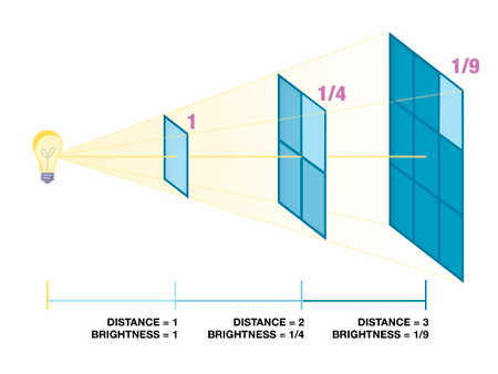
Thus the square law propagation of light:
The intensity of light varies according to the square of the change in distance from light to illuminated surface.
So, if you increase the distance by two, the light intensity becomes one fourth – 2 f-stops, not 1f. If you move the light in to one half the distance, the intensity increases by 2 f-stops.
To affect a 1f gain in light intensity, you would move the light in by a factor of .707 (from 10 feet to 7 feet). Moving the light out by a factor of 1.414 (to 14 feet) will result in a loss of 1f.

11 REMOTE CONTROLS
First try swapping both the CyberSync™ Trigger Transmitter or Cyber Commander™ and all receivers to a new frequency than the one you are currently using to rule out interference. If that does not work, try new batteries on all the components that require them.
The x-sync speed is determined by the camera and radio tripper (in the case of the CyberSync™ system, either the Cyber Commander™ or CyberSync Trigger Transmitter). The delay time of the CyberSync™ system is 1/4000 second. It can sync up to 1/2500 second on capable cameras and flash units. Most modern DSLR cameras max around 1/160 - 1/250 second, either with a sync cord or with a CyberSync™ component.
This flashing red LED indicates that the battery is low or has a weak connection. You will need to replace the battery.
Rapid firing can be caused by a very low battery in the transmitter. You will need to replace the battery.
First, make sure that both the transmitter or Cyber Commander™ and the receiver(s) are on the same channel / frequency. On the CSRB+, the gray arrows on the frequency / channel dial are pointing to the correct number. On the CSRB, CSR, and CSR+, make sure that the dark notch on the frequency / channel dial is facing the correct number. On the CyberSync™ Trigger Transmitter make sure the red arrow on the frequency dial is facing the correct number.
The transmitter's effective range can be affected by the state of the battery in the transmitter. If your range seems to drop under familiar conditions, it may be time to change your battery. Range can also be influenced by objects too near the CST2 antenna or by solid objects obstructing the line of sight path to the receiver's antenna.
12 PORTABLE POWER
The Vagabond™ systems are NOT designed to operate standard modeling lamps continuously. With essentially all battery/inverter type supplies, a flash unit’s modeling lamps are not generally used because their power draw would quickly deplete the battery, slow recycle times dramatically, and could overheat the inverter. To maximize battery life, the modeling lamp in each connected flash unit should be turned OFF, only turned on for brief previews to compose the lighting. However, with the DigiBee flash units and their permanent LED modeling lamps, the Vagabond systems may be used to power a unit with the modeling lamp. See the chart below for expected battery life (per charge) when using a Vagabond system to power a DigiBee unit, using the modeling lamp.
| DigiBee DB400 Flash Unit | DigiBee DB800 Flash Unit | |
| DigiBee Typical Performance with Vagabond VLX |
|
|
| DigiBee Typical Performance with Vagabond Mini Lithium |
|
|
Note: These specs are for DigiBee flash units only, and ONLY when the modeling lamp is used (flash function turned OFF). With the Vagabond Mini™ Lithium system, the battery cannot be used to power a modeling lamp over 120 Watts, even briefly. For Einstein™ users, we offer 25W modeling lamp for reduced-intensity modeling lamp usage (part # 25W), though this lamp should still only be used for brief composition. For AlienBees™ or White Lightning™ users, the supplied modeling lamps can be replaced with lower 25 Watt or 40 Watt household bulbs to allow brief usage of modeling lamps for composition. These standard Edison-type bulbs can be purchased locally. If you choose to use a lower-wattage modeling lamp briefly, the units should be set to extinguish the modeling lamps during recycle to minimize recycle time.
The lifespan of the battery in your Vagabond™ Lithium Extreme or Vagabond Mini™ Lithium system will vary based on a number of factors including frequency of use; power load while in use; charge level, environmental conditions, and ambient temperature (both when the unit is in use and in storage); and overall battery age.
The VLXBAT battery in the Vagabond™ Lithium Extreme system, when properly used and properly taken care of should deliver approximately 1000 to 1500 charge / discharge cycles. The useful life of the VLXBAT can be 10+ years. When the battery capacity drops to 50% or lower (when the number of full power flashes, per wattsecond rating, per battery charge is halved), it is recommended that you replace the battery.
The VMB8.8 battery in the Vagabond Mini™ Lithium system, when properly used and properly taken care of should deliver approximately 200 to 300 charge / discharge cycles. The useful life of the VMB8.8 can be 2 to 4 years. When the battery capacity drops to 50% or lower (when the number of full power flashes, per wattsecond rating, per battery charge is halved), it is recommended that you replace the battery. For safety and best performance, the battery in your Vagabond Mini™ Lithium system should be replaced after 4 years, regardless of capacity.
Yes. All Paul C. Buff™ flash units, with exception of the Einstein™ unit, consume about 3 Watts when turned ON and idling between shots. The Einstein™ unit uses more power because it contains a sophisticated switching power supply which is always providing power to the controls and LCD (and CyberSync™ transceiver, if connected) whenever it is connected to an active power source. When the Einstein™ unit is inactive (having been turned OFF by means of the POWER button or by using the Cyber Commander™ remote control system), it still consumes approximately 3 Watts from its power source. When the unit is turned ON, with the LCD graphic user display lit and operating, the Einstein™ unit draws more “idling” power from its power source than other Paul C. Buff™ flash units. At 120 Volts AC input, it consumes approximately 7 Watts when idling between shots. At 230 Volts AC input, the power consumption rises to approximately 12.5 Watts. This presumes the modeling lamp is turned OFF as the constant draw of the modeling lamp in any unit will rapidly deplete the battery.
So, if one uses the Vagabond™ Lithium Extreme system or the Vagabond Mini™ Lithium system to power any flash unit for an extended period of time, the equipment is consuming power from the battery, even if the unit is not being flashed or recycled. Keep in mind that there is an energy budget: the Vagabond™ charger puts energy into the battery, and the inverter and its load (whatever that might be, AlienBees™, White Lightning™, or Einstein™ units) is constantly drawing against the amount deposited. The draw is slow when the lights are idling and rapid when the lights are being recycled. The energy budget is depleted even more quickly when using multiple lights. During extended shooting sessions, one will likely not get as many shots from the Vagabond Mini™ Lithium battery when using the Einstein™ unit as one might get when using an AlienBees B1600 or two B800 units, even though the stored energy in the lights is the same for all three scenarios (640 Wattseconds).
If flash units are left ON while connected to a Vagabond™ system, even if the units are not fired and the modeling lamps remain turned off, the units still draw power and have the capability to discharge a battery completely over time, depending on the amount of time, the ambient temperature of the environment, the age of the battery, etc. As the EInstein™ units draw more power that the AlienBees™ and White Lightning™ units, an idling Einstein™ unit left ON while connected to a Vagabond™ system will deplete the battery more quickly.
Ultimately, it is easy to understand that the Vagabond™ battery’s energy budget is not infinite, and the actual number of shots one may be able to make on a single battery charge depends not only on the flash unit(s) power setting, but also on the continuous power consumption of the light(s) being powered. To extend the useful operating time for a single battery charge and level the field between Einstein™ units and other Paul C. Buff™ units, one can simply turn the Vagabond™ system OFF between groups of shots, or turn the Einstein™ unit(s) OFF between groups of shots.
Yes, the batteries in both the Vagabond Mini™ Lithium and Vagabond™ Lithium Extreme systems are certified for global air travel. Lithium batteries are regulated for air travel by both the U.S. Department of Transportation (DOT) and the International Air Transport Association (IATA) and based on the specifications of the battery, the current DOT and IATA regulations indicate that domestic customers should able to travel by air with a Vagabond™ system as carry on baggage.
You must check with your individual airline carrier before traveling with any Vagabond™ component each time that you wish to travel by air in order to find out the updated, applicable regulations for your specific flight based on the specific items that you wish to travel with. To determine eligibility for travel, you may be asked for certain specifications of the battery which are both printed on the battery and provided in the manual (sent with the product and available for download here).
***Before traveling, be sure to download and print the travel documentation for the battery: Vagabond™ Lithium Extreme / Vagabond Mini™ Lithium
Vagabond™ Lithium Extreme battery specifications for reference:
- lithium iron phosphate battery
- 158.7 Watt-hours (Wh)
- 6.2 Amp-hours or Ampere-hours (Ah)
- 25.6 Volts (V)
Vagabond Mini™ Lithium battery specifications for reference:
- lithium ion battery
- 130 Watt-hours (Wh)
- 8.6 Amp-hours or Ampere-hours (Ah)
- 14.8 Volts (V)
The Vagabond™ Lithium Extreme system and Vagabond Mini™ Lithium system are designed to provide portable power for Paul C. Buff™ flash units; however, it can be used to power other brands of flash units as well.
While we are not able to test our Vagabond™ systems with all of the various brands and models of flash units available, we have tested the systems with a number of units and received excellent feedback from customers who are successfully using the system to power multiple brands of flash units. Based on our tests and this customer feedback, we have determined that the Vagabond™ systems should work with nearly all standard photographic flash units (both analog and digital). With multi-voltage flash units, the Vagabond Mini™ Lithium system may only work to an extent and the system should only be used to power one flash unit of this type at a time.
To find out about your particular flash unit, contact our Customer Service Team and we’ll be happy to provide you with any information that we have available for that specific unit.
While we feel confident that our Vagabond™ systems can be used to power various brands of flash units, we cannot make any claim for suitability with any individual products made by other manufacturers, nor can we accept any liability for any damage that might be caused to such equipment. We do, however, warranty the Vagabond™ systems themselves as well as any Paul C. Buff™ equipment powered.
The Vagabond™ Lithium Extreme, Vagabond Mini™ Lithium and previously offered Vagabond™ II system (discontinued) may be used to power non-flash continuous loads for small electrical appliances such as fans, computers or radios. Please note, however, that each system has a maximum continuous power load limit in such applications:
| Vagabond™ System | Maximum Continuous Power Load |
|---|---|
| Vagabond™ Lithium Extreme | 400 Watts |
| Vagabond Mini™ Lithium | 120 Watts |
| Vagabond II (discontinued) | 300 Watts |
If a continuous load is used in conjunction with flash unit use, this number should be reduced. It should be noted that when the Vagabond™ system is used to recycle flash units, the output voltage will not remain at 120 VAC; it will drop lower during the recycle period of the lights. Therefore, equipment that requires continuous 120 VAC should not be used in conjunction with flash units. To the best of our knowledge, the momentary low voltage will not affect laptops connected via their battery chargers. However, AC-powered computers will likely crash under the "brown out" conditions and likely draw more than 120 watts. If you plan to power auxiliary equipment, you should consult the product’s manual and / or check with the product manufacturer to determine the power consumption. It is not generally advisable to operate flash units and continuous power loads at the same time. Please note that with the Vagabond™ II system specifically, as in any lead acid battery system, the amount of power available from the battery depends upon operating temperature. Operating temperatures substantially higher than, or lower than room temperature will result in less power being delivered from the battery.
13 REPAIR / WARRANTY
How do I know if my equipment is still under warranty?
You may contact us directly to see if you your equipment is still under warranty.
| Product | Warranty Period |
| DigiBee (DB400 / DB800) | AlienBees™ (B400 / B800 / B1600 / ABR800) | Einstein™ (E640) | 2 years |
| White Lightning™ X-Series (X800 / X1600 / X3200) | 5 years |
| The Vagabond™ Lithium Extreme System (VLX) and all system components (VLX, VLXINV, VLXBAT, and VLXCHG) |
1 year |
| The Vagabond Mini™ Lithium System and all system components (VM120, VMB8.8A, and VMC3A) |
1 year |
| The CyberSync™ System (CC, CST, CSXCV, CSR, CSR+, CSRB and CSRB+) |
2 years |
| The LG4X™ Wired Remote Control | 2 years |
| All Other Accessories (softboxes, the PLM system, travel gear, reflectors, the Moon Unit, stands, etc.) |
1 year |
| All Hardware and Accessories (individually purchased – replacement flashtubes, replacement lamps, cords, clips, adapters, etc.) |
1 year |
See our Service and Repairs page for complete details.
See our Returns page for complete details
For customers in Canada, we recommend our Canadian authorized service and repair center, Service Camera Pro, for both warranty and non-warranty repairs. Using this repair center in Canada allows our Canadian customers to have quality service for their equipment without the added expenses and extended turnaround time involved in shipping the equipment across the border to our facility. Read more about Service Camera Pro services here.
All other products MUST come to Paul C. Buff, Inc.™ for repairs and service. We DO NOT recommend service from any other location. Any work or service performed by individuals or service centers other than Paul C. Buff, Inc.™, or Service Camera Pro, may void your product warranty.
Still have a question about your order?
Contact details
- Ellekomstraat 64
- 2573XG Den Haag
- Nederland
- Tel: +31(0)85 060 1820
- E-mail: [email protected]
Contact us

© Copyright 2026 - Paul C. Buff Europe Webshop | Flash Lighting and Newborn Studio Kit | Realisatie InStijl Media